Skh Relay Ladder Diagram Examples
PLCs have unconnected in the controls market and are victimised throughout the world. Over time they have hi-tech to become Sir Thomas More user congenial, efficient, smaller and less expensive. Different types of programming languages have also been developed for PLCs but the most often used is smooth Run Logic.

The Origins of Run Logic – Relay System of logic
Think for a moment it's 1980. You'rhenium cruising in your brand new Edsel Bryant Ford Pinto on the way to your job at the localized Rubik's Regular hexahedron plant. You have a busy day ahead since the plant is being redesigned for the inexperienced Rubik's Revenge model due out next twelvemonth. The relay panels you employment along need to be rewired to accommodate the convert in output size of it, from the original 3x3x3 sizing to the newborn 4x4x4 role model.
These relay panels lie in of numerous electromechanical relays that are wired together to perform a foreordained function in the engraft. The cuneate opening and closing of relay contacts on the panel gives the scheme the ON/OFF control it inevitably in the manufacturing litigate. For instance, when the cube's determine is in position a switch will close. This switch energizes a relay coil, which in turn closes the normally open contact for the injection pump. The pump fills the mold with liquid plastic and the cube begins to use up shape.
Using this combination of switches, relays, coils and contacts is referred to every bit Relay Logical system. Relay logic is a dependable controls method hush up in controlled use today. But the cost associated with IT in terms of clip-consuming logic changes, mechanical failures over time and extensive wiring and distance requirements has forced many industries to reconsider their insure needs. What they disclosed was the PLC.
The Social organisation of Ladder Logic/How to Read Ladder Logic
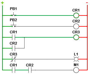
The structure behind ladder logic is founded on the electrical ladder diagrams that were used with relay logic. These diagrams authenticated how connections between devices were made on relay panels; they are called "ladder" diagrams because they are constructed in a way that resembles a ladder with two vertical track and rungs between them. The positive power rail (on the left) flows to the dissident power rail (on the right) finished the fleshly devices abutting on the rung. The example below shows a ladder plot with pushbuttons (PB), control relays (CR), a motor (M) and a light (L).
Similarities with Ladder Diagrams
Ladder logic was designed to have the very look and feel as electrical ladder diagrams, simply with ladder logic, the physical contacts and coils are replaced with memory bits. Let's take a look.
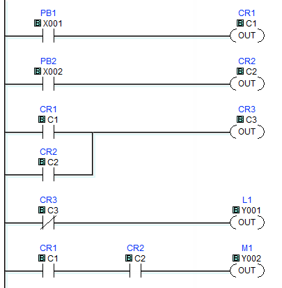
For this program, the electrical relay logic's run diagram is duplicated with ladder logic; no more hard-wired system of logic, but memory locations instead. Some of these storage locations are old internally and others are victimised with external inputs and outputs. To monitor and operate real world devices, they bequeath need to be wired to I/O modules.
For this particular PLC, these inputs and outputs are allotted to X and Y memory addresses like the X001 seen with PB1. This normally open contact's state is understand from the input on the I/O module where the physical pushbutton is abutting. On the former hand, each Y bit leave have an output twist wired to it as seen with the light controlled aside Y001. All of the other locations are assigned to internal bits that we can consumption as needed.
Nonpareil side note, today's PLC CPUs offer many types of functions, non just simple contacts and coils. Math, Transmutation Registers, Drum Sequencers, etc., are available to economic aid in programming.
Execution of Ladder Logic
Typically ahead starting to execute the system of logic, the CPU reads the physical inputs tied to the I/O modules to update their status in the C.P.U.'s memory table. Then, starting at the top left of the plan, the CPU works its way down the rail executing each rung or sub rung from left to right. So if PB1 is ironed, the CPU will turn Along CR1. Since CR1 has altered states, in stave 3 the C.P.U. volition trip CR3. CR3's ordinarily-closed state is used in rung 4, so the CPU will then sour OFF L1.
Even though we still refer to coils and contacts in ladder logic, remember that they are memory representations, non true devices. Once the CPU reaches the dying rundle it bequeath update the real worldwide outputs, and so cringle back and endure it entirely again. This process wish continue as long arsenic the CPU is powered and in the RUN mode.
The prison term it takes the CPU to perform one pass and loop plunk for to the beginning is well-known every bit glance over time. Scan clock time can be important to applications where timing is critical. Subroutines and special purpose I/O modules can live used to help reduce the scan time if needed.
The System of logic Behind The Ladder
So what logic can ladder system of logic really execute? With the increasing demand for functionality and ease of use, many of today's PLCs incorporate function blocks with ladder logic. The bodily structure of the program is still run with the many complex instructions beingness function blocks. So to respond the query, permit's look at a few examples:
- Boolean Logic: The ON/OFF, TRUE/Treacherously algebra of binary systems, the basics of which are AND, OR and NOT operators. To order it simply, rung 5 in our encode inevitably CR1(C1) AND CR2(C2) to turn ON motor M1 (Y002).
- Timing: Timer instructions are getable to allow for along-delayed Beaver State turned-delayed events. Once triggered, the timekeeper volition turn its associated turnout ON (along-delay) or OFF (off-delay) after the set time has elapsed.
- Counting: Calculate-up and count-down functions increase or decrease the riposte prize on every transition of the stimulant.
- Comparisons: Compare instructions are accessible to determine if values are to a lesser degree, equal to or greater than each other.
- Mathematics: These instructions not only allow for the simple summation and subtraction but besides for Sir Thomas More convoluted operations like tangents, wholesome roots, etc.
- Special functions: These let in PID loops, communication instruction manual, shift registers, drum sequencers, ramp generators, etc.
Try an Exercise
If you would like to try an practice session in ladder logic, AutomationDirect has created a beginner's programming exercise. This exercise was actually created for the Boy Scouts of America to avail teach ladder logic to future PLC programmers. It uses the simulator included with the Do-to a greater extent Fashion designer programming software for our Do-more PLC series.
The software is free and you do not need some hardware, then try information technology. Download the software here.
Learn More about Ravel Logical system
In that location is a lot more than to se; we've only begun to scratch the surface. See how we can help you Learn More about PLCs and get PLC Training!
Source: https://library.automationdirect.com/understanding-ladder-logic/
Posted by: sebastianlindow.blogspot.com